AROBS Transilvania – custom software development company
Blog
Robotic arm – an Intelligent Robotic System for Text Typing on a Computer, using neuronal networks, machine vision, and deep cam algorithms – how hard is it to create one?
Artificial intelligence and machine vision have an increasing role in digital image processing, given that software development has paved the way for complex technological possibilities.
The following study elaborated by Victor P., who is an Embedded C/C++ developer and engineer in AROBS, while at the same time a passionate student of Automotive Embedded Software Master at the Politehnica University of Timișoara, shows the basics of creating a robotic arm system that can autonomously type, using neuronal networks, machine vision, and deep cam algorithms.
Similar studies have helped the development of specific automotive software engineering services requirements.
Keywords: machine vision, neuronal networks, deep cam algorithms, handwritten text interpretation, robotic arm, embedded software services, image processing, pinhole camera model.
Spoiler – watch the Proof of concept video about this intelligent robotic arm here and at the end of the article.
‘’The important thing is not to stop questioning.’’
Albert Einstein
Machine vision? Neural networks? Object detection? What is all this? How does it work? And the most important question: How can I use them in my own projects in order to automate different processes? These were my first questions in the field of Machine Vision and neural networks, the questions I asked myself as a student in my last year of bachelor’s degree, specializing in Automation and Informatics at the Technical University of Moldova.
The idea of a robotic arm – tired of typing
Like all students, I was tired of typing text on a computer, so having the spirit to automate various processes, I came up with the idea of using artificial intelligence, machine vision, and other technologies for a robotic hand to type text, by hand, autonomously from written concepts. So that’s how the idea for my bachelor’s thesis was born.
Main features of an intelligent robotic system
The basic concept of the project is based on the use of machine vision techniques, neural networks, positioning techniques in 3D space through the WEB cam, and of course, the creation of a GUI (Graphical User Interface) for the interaction between the intelligent system and user or customers.
The robotic arm will automatically cover the handwritten text. The text is acquired through a WEB cam after which it is sent to the server for interpreting and extracting the text. After the text is processed, the robotic arm equipped with another WEB cam, detects the letters in real-time, from the keyboard.
By using the deep cam algorithms, it traces the trajectory of the arm’s movement from the current point to the required letter on the keyboard. This process is cyclically repeated for each letter in the word.
Acquisition and interpretation of the handwritten text
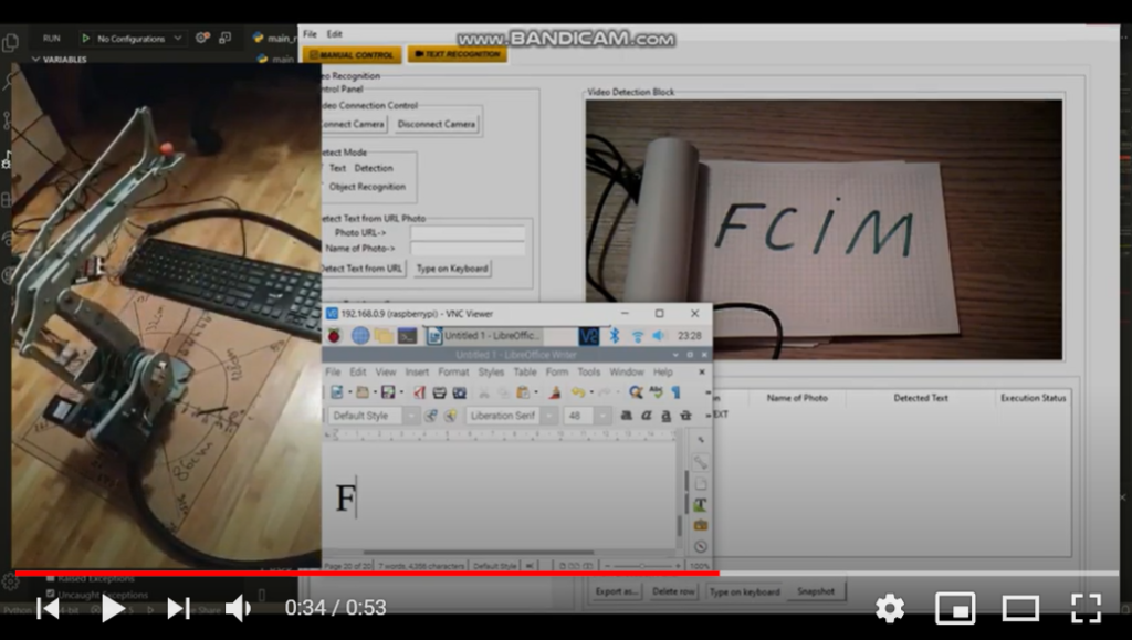
In order to interact more comfortably with the user, a GUI (Figure 1) is created, that offers the full set of expected features. The user only needs to place the text under the camera and take a picture through this application. After the picture is taken, it is transmitted to the neural networks of Microsoft cognitive services (Figure 4). This method was chosen to increase the productivity and speed of the program. Also, due to these services, it reaches a 90% accuracy of text detection (Figure 3).
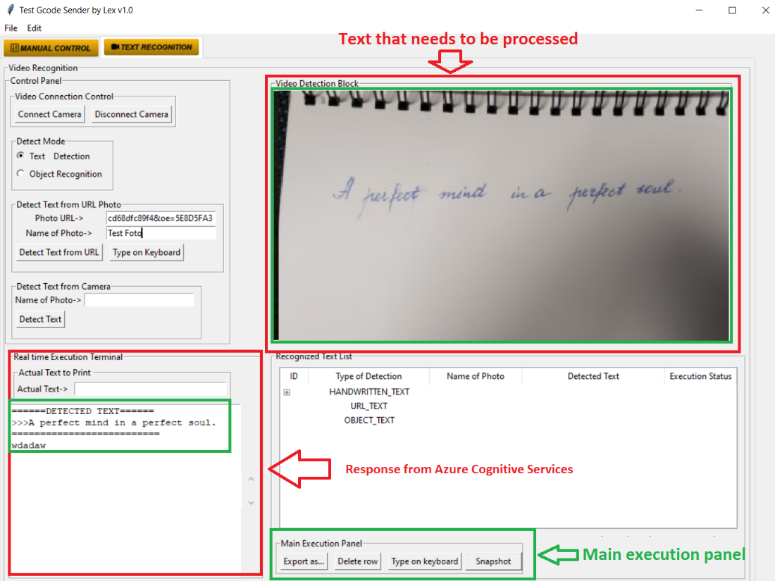
Figure 1. Graphical User Interface (GUI)
After the text is extracted from the image, it is transmitted back to the algorithm, so that it can be typed by the robotic arm, but this is already the next step.
The photo which is purchased through the webcam is transformed into a matrix (X, Y, Z) (Figure 2) where X represents – the number of pixels on the X-axis, Y- the number of pixels on the Y axis, 3 – the number of color channels, in this case, RGB (Red, Green, Blue). For each color, a two-dimensional array of size (X, Y) is formed in which each cell with coordinates (Jxy) represents the pixel intensity for each separate channel.
After the successful transformation, the photo is transmitted via API (Application Programming Interface) technology to the Microsoft servers.
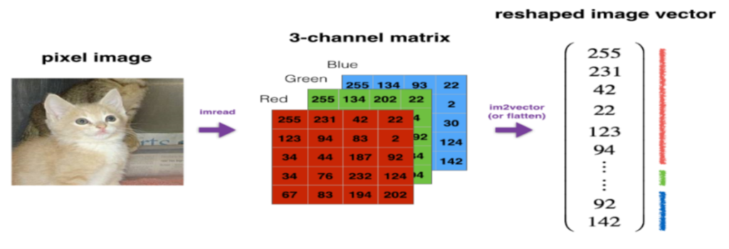 Figure 2. RGB matrix formation
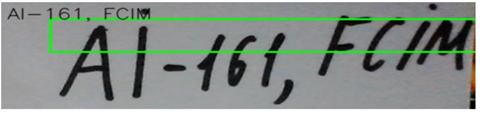
Figure 3. Example of a response from Azure Cognitive Services
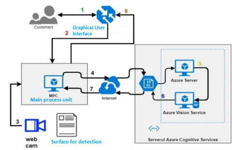
Figure 4. Block diagram of the system for acquiring and extracting handwritten text.
Letter detection on the keyboard – steps
The interpretation of the letters on the keyboard is done with the help of neural networks.
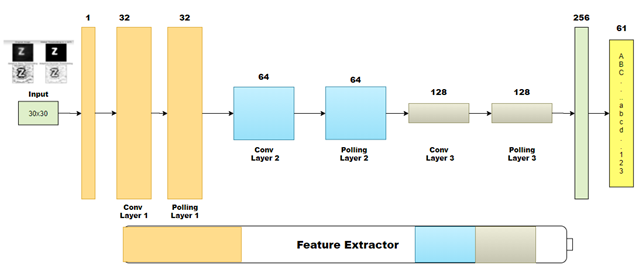
The neural network used in this project has the role of interpreting the already processed image by digital image processing technologies. Image segmentation is done independently, this assumes that the image transmitted for interpretation to the neural network can only be one letter corresponding to a single class of letters. The neural network used in this project has a much higher processing speed, the detection speed varying between 15-20ms.
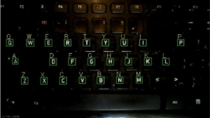
1 Step: Acquisition via WEB Cam of keyboard image.
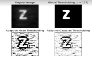
2 Step: Binarization of image.
3 Step: Segmentation of image, for each letter apart.
4 Step: Send image from the previous step for interpretation to CNN (Convolutional Neuronal Networks).
5 Step: Get Output Response from CNN and crop every detected letter from Keyboard.
Visual inspection algorithm
In some situations, for various reasons, not all letters on the keyboard are recognizable. The visual inspection algorithm is created to reduce such situations. Its main purpose is to detect letters that were not recognized.
This feature is realized by using the algorithm that iteratively checks each letter recognized by the neural network. Each recognized letter is added to an internal database of the program. The first stage of the algorithm is to compare the current database with the reference one (in this database are present all the letters together with the neighboring letters, the neighboring letter on the right and the neighboring letter on the left), checking and finding the letter that was not recognized. The algorithm is using the information from the current database (the recognized letters and their position in the 3D space are present).
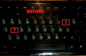
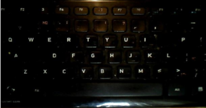
Figure 5. Key recognized without Visual Inspection Algorithm.
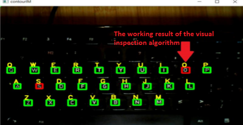
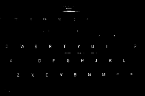
Figure 6. Key recognized after Visual Inspection Algorithm is applied.
Mapping of detected keyboard letter is performed like is stipulated in next image:

Figure 7. Mapping in the cartesian system of coordinates of letters.
Calculating the distance between the letter and the robotic arm
Typing the letters by the robotic arm is done by linking the coordinates of the robotic arm to the coordinates of the key corresponding to the required letter (Figure 7).
This binding is done by photometry techniques, which show the possibility of using the webcam to find the position of the object in the coordinate system – global (X, Y, Z) by manipulations with the corresponding image. The technique given is called the Pin Hole Camera Model and is based on the darkroom model.
It works based on the design of the point in the global coordinate system on the image plane. It performs the calculation of the distance between two points. Knowing the position of the key and the robotic arm it is possible to perform the necessary calculations to establish the trajectory of movement to the required letter (Figure 9).
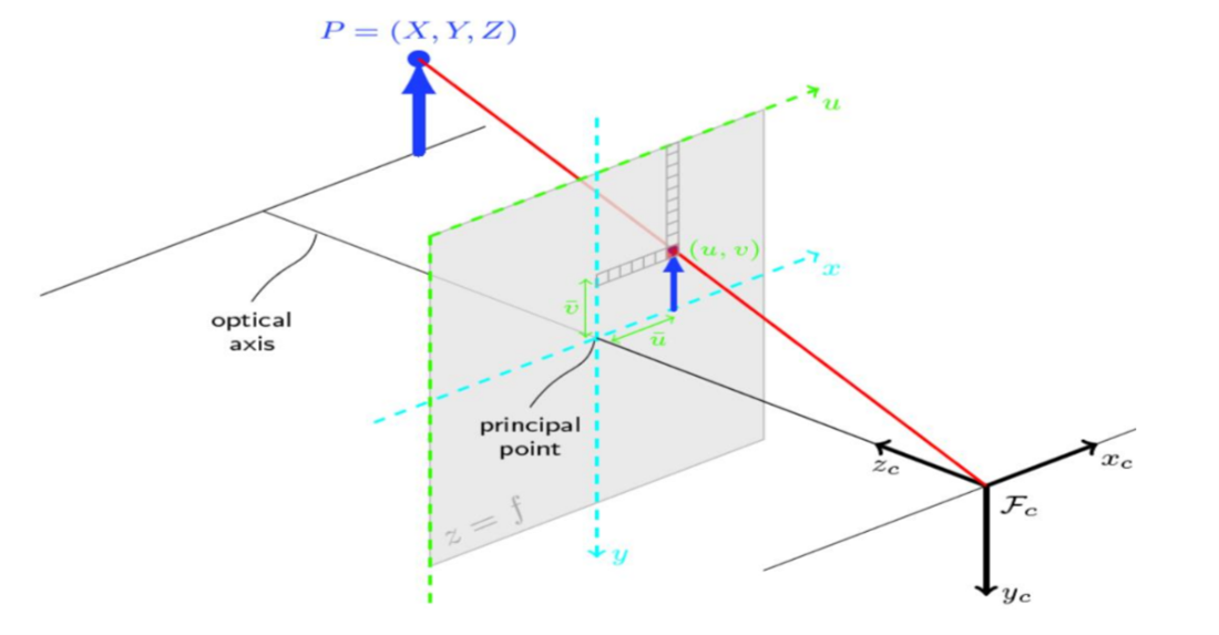
Figure 8. Pin Hole Camera Model used for calculating the distance between the arm and letter on the keyboard
In order to transform the global coordinates (X, Y, Z) into the coordinates (u, v) of the image plane, it is necessary to know a set of parameters such as:
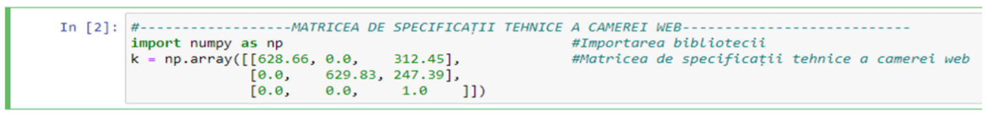
- Camera specification matrix (camera model) – this matrix is obtained by performing camera calibration. The OpenCV library already offers integrated functions that have the ability to generate the webcam specification matrix.
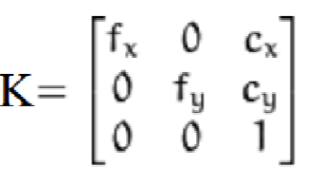
Where:
- fx – the focal length on the x -axis of the camera measured in pixels.
- fy– the focal length on the y-axis of the camera measured in pixels.
- Cx – x coordinate of the optical center of the camera.
- Cy – y coordinate of the optical center of the camera.
Following the calibration of the camera through the functions in the OpenCV library, the model of the webcam used in this project is obtained.
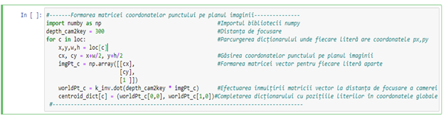
Knowing the necessary parameters, it can determine the global coordinates of the point with high precision according to the formula below.
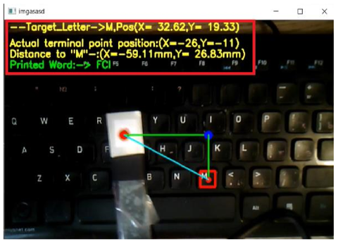
Figure 9. Result of the detection using Pinhole Camera Model
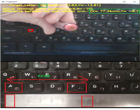
Figure 10. Calculation accuracy of the algorithm
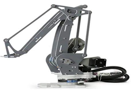
Figure 11. Robotic Arm
Conclusion – the effect of artificial intelligence on digital image processing
This study proves the enormous possibilities of artificial intelligence in digital image processing, offering a wide range of possible variants of use depending on the wishes and needs of the engineer.
The only disadvantage is that it requires a modern technical material base and large computing resources.
Machine vision is a branch that is increasingly used in all areas of life, which involves the development of this branch and as a result is an area of growing interest for subsequent research studies, which in relation to this study will focus on solving real problems.
For more information please contact Victor P. writing us a message.
Proof of concept – Let’s see how it works
Click on the picture below to check out exactly how this robotic arm types.
Or just click on the Youtube button below to see the Proof of concept.

If you have found this study interesting and you are a like-minded person, don’t forget about the opportunities for you in AROBS.
PuzzleIn with us!